In this guide, we’re going to take a close look at CNC milling. You’ll find out what it is exactly and how it works. We’ll also go through its history, step by step, from the early days of manual milling to the high – tech CNC systems we have now. You’ll understand the good and not – so – good points of CNC milling when compared to other ways of making parts.
We’ll dig into the whole process, starting with how to read and plan from a part drawing, all the way to making sure the final part is top – quality. There’s a lot to learn about the different milling methods, which materials are best for milling, and how to save money and work more efficiently. And we won’t stop there – we’ll also look ahead to see what new things are coming up in the world of CNC milling.
This guide is here to help everyone, whether you’re just starting out and want to learn the basics, or you’re an experienced hand looking for some new ideas. If you’ve got some know – how in this area, we’d love to hear from you. Just leave your comments and share your thoughts. Now, let’s start exploring CNC milling!
What is CNC Milling?
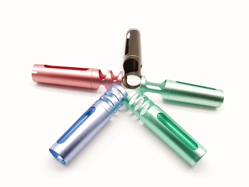
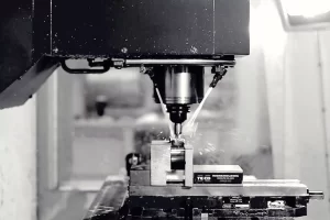
CNC milling is a Computer Numerical Control machining process. It utilizes pre – programmed instructions to control the cutting motion of the milling machine’s cutting tools on the workpiece, removing material to obtain the desired part shape and dimensions. During the CNC milling process, the worktable of the milling machine can move in multiple directions (usually the X, Y, and Z axes), and the cutting tool can also rotate. Through the relative movement of the two, the milling of the workpiece is achieved. For example, to machine a mechanical part with complex grooves and bosses, CNC milling can precisely cut at different positions of the workpiece according to the program settings, removing the excess material and thus manufacturing a part that meets the design requirements.
What’s the History of CNC Milling?
Origin of Milling Technology: The Earliest Manual Milling
The origin of milling can be traced back to ancient times. Early milling operations were completed by hand. Craftsmen used simple tools, such as hand – held cutting tools similar to the shape of modern milling cutters, to cut on the workpiece surface. These tools were usually made of stone, bronze, or iron. For example, in ancient Egypt, craftsmen already began to use crude milling tools to process wood and some soft metals for making furniture, architectural decoration components, and simple weapons. The processing at that time was very slow and had limited precision, mainly relying on the craftsmen’s experience and skills. This manual milling method lasted for a long time and did not begin to change significantly until the emergence of mechanical power.
The Promotion of the Industrial Revolution on Milling Technology
The Industrial Revolution was a crucial turning point in the development of milling technology. With the invention and application of power sources such as the steam engine, machining equipment had a stable and powerful power. In 1818, American engineer Eli Whitney manufactured the first milling machine. The appearance of this milling machine marked the transition of milling from manual operation to mechanical processing. During the Industrial Revolution, the design and function of milling machines were constantly improved. It began to adopt more precise transmission mechanisms, such as gears and lead screws, which made the movement between the cutting tool and the workpiece more precise. The worktable of the milling machine could achieve more complex movements, such as longitudinal, transverse, and vertical feeds, so that various – shaped parts, such as planes, grooves, and gears, could be machined. Moreover, with the development of the steel industry, the structure of the milling machine was more solid and durable, could withstand greater cutting forces, and the machining efficiency was greatly improved.
The Birth and Development of Numerical Control (CNC) Technology
Early Exploration Stage
The concept of numerical control technology can be traced back to the late 1940s and early 1950s. At that time, the US Air Force, in order to meet the processing needs of complex aviation parts, began to fund research on the technology that could control the movement of machine tools through digital instructions. In 1952, the Massachusetts Institute of Technology (MIT) successfully developed the first numerically – controlled machine tool, which was a milestone in the development of numerical control technology. This machine tool input digital instructions through punched tape to control the movement of the machine tool, opening a new era of automated machining of machine tools.
Mature Technology Stage
With the continuous progress of electronic technology, especially the rapid development of computer technology, numerical control technology gradually evolved from the early hard – wired numerical control (NC) to computer numerical control (CNC). The CNC system uses microprocessors and computer software to control machine tools and has higher flexibility and precision. In the 1970s – 1980s, CNC milling technology was widely used. CNC milling machines can precisely control the tool path and, through pre – programmed instructions, can achieve complex three – dimensional surface machining, such as the machining of aero – engine blades and automobile molds.
Intelligent and Networked Stage
Entering the 21st century, CNC milling technology is developing towards intelligence and networking. Intelligent CNC milling machines can automatically adjust machining parameters according to real – time data during the machining process, such as cutting force and tool wear, to ensure machining quality and efficiency. Networking enables multiple CNC milling machines to be connected through a network, realizing remote monitoring, programming, and production management, greatly improving the production flexibility and management efficiency of manufacturing enterprises.
What are the Advantages and Disadvantages of CNC Milling?
Advantages of CNC Milling
High – Precision Machining Ability
CNC milling can achieve very high precision. Modern advanced CNC milling machines can have a positioning accuracy of up to ±0.001mm or even higher. This is because CNC milling machines are equipped with high – precision transmission components, such as ball screws and linear guides, which can precisely control the movement of the worktable in all directions. At the same time, the CNC system can finely program and control the tool path to ensure extremely high position accuracy of the tool cutting on the workpiece. For example, when machining precision molds, this high precision can ensure the dimensional accuracy and surface quality of the mold cavity, so that the produced plastic products have accurate dimensions and a smooth surface.
High Flexibility
CNC milling is very flexible in machining parts of different shapes and sizes. By modifying the instructions in the CNC program, the shape, size, and process parameters of the machined part can be quickly changed. This flexibility makes it very suitable for small – batch and multi – variety production modes. For example, in a machining workshop, when it is necessary to produce a variety of mechanical parts with different specifications, the operator only needs to rewrite or adjust the CNC program to machine different – shaped planes, curved surfaces, grooves, and various complex three – dimensional shapes on the same milling machine, without the need to frequently change tooling fixtures and molds as in traditional machining methods.
Higher Machining Efficiency
In batch production, CNC milling shows high efficiency. On the one hand, the tool path planning can be optimized to reduce the air – travel time and cutting time. For example, adopting efficient helical milling or contour – milling strategies can quickly remove a large amount of material. On the other hand, CNC milling machines can achieve multi – axis simultaneous machining, such as five – axis simultaneous CNC milling, which can cut multiple surfaces of a part at the same time, greatly reducing the machining process and time. Moreover, CNC milling can run unattended for a long time. As long as the program and machining parameters are pre – set, machining can be continuously carried out, improving the utilization rate and production efficiency of the equipment.
Wide Material Adaptability
CNC milling can machine almost any material, including various metals (such as steel, aluminum, copper, etc.), plastics (such as ABS, PC, etc.), wood, and composite materials. For different materials, only the appropriate cutting tools and cutting parameters need to be selected for effective machining. For example, when machining metal materials, carbide cutting tools can be used, and the cutting speed, feed rate, and cutting depth can be adjusted according to the hardness and toughness of the metal; when machining wood, high – speed steel cutting tools can be used, and a higher cutting speed and smaller cutting force can be adopted to avoid the surface of the wood from tearing.
Good Surface Quality Control
By reasonably selecting cutting tools, cutting parameters, and machining processes, CNC milling can produce parts with high – quality surfaces. For example, during finishing, using a ball – nose milling cutter and adopting a small feed rate and cutting depth can obtain a very smooth curved surface. At the same time, some advanced CNC milling machines are also equipped with tool compensation functions and on – line measurement systems, which can adjust the position of the tool and cutting parameters in real – time, further improving the surface quality. This good surface quality control ability makes CNC milling have a great advantage in manufacturing products with high requirements for appearance and precision, such as electronic product shells and automobile parts.
Disadvantages of CNC Milling
High Equipment Cost
The price of CNC milling machines themselves is relatively expensive. This is because they include complex mechanical structures, high – precision transmission and control systems, and advanced numerical – control devices. The price of an ordinary CNC milling machine may be several hundred thousand yuan, while the price of a high – end multi – axis simultaneous CNC milling machine may be as high as several million yuan. In addition, in order to ensure the normal operation and accuracy of the equipment, regular maintenance and upkeep are also required, which will increase the equipment’s use cost. For example, high – precision ball screws and linear guides need to be regularly lubricated and their accuracy adjusted, and the CNC system also needs to be regularly updated with software and have fault repairs.
High Programming Requirements
CNC milling requires professional programmers to write machining programs. The programming process involves complex contents such as three – dimensional modeling of parts, tool – path planning, and setting of cutting parameters. For complex parts, the programming difficulty will be greater. For example, to machine an aero – engine blade with a complex curved surface, the programmer needs to have profound mathematical knowledge and rich programming experience to accurately generate the tool path and ensure the shape accuracy and surface quality of the blade. Moreover, programming errors may lead to part scrapping or equipment damage, so the programming process needs to be very rigorous.
Tool Wear Problem during Machining Process
During the CNC milling process, the cutting tool will wear due to factors such as friction with the workpiece material and cutting force. Tool wear will not only affect the machining accuracy and surface quality but also increase the production cost. Different materials and cutting parameters have different effects on tool wear. For example, when high – speed cutting hard – metal materials, the tool’s wear rate will be relatively fast. To ensure the machining quality, the tool needs to be frequently replaced, which will increase the machining cost and reduce the machining efficiency. Moreover, the monitoring and judgment of tool wear are also relatively complex and require a certain amount of experience and professional equipment.
Waste Generation Problem
Since CNC milling is a subtractive manufacturing process, a large amount of waste will be generated during the machining process. These wastes are usually non – recyclable, especially when machining metal materials, metal chips will be produced. The treatment of waste will not only increase the production cost but also have a certain impact on the environment. For example, a large amount of metal chips need special recycling equipment for collection and treatment, otherwise, they may pollute the environment, and the recycling process also requires a certain cost.
CNC Milling vs. CNC Turning vs. 3D Printing
How Does CNC Milling Compare with Other Machining Methods?
| Comparison Items | CNC Milling | CNC Turning | 3D Printing |
|---|---|---|---|
| Machining Principle | The tool rotates, the workpiece is fixed, and cutting is achieved through the movement of the worktable | The workpiece rotates, the tool is stationary, and the tool cuts axially and radially along the workpiece | Layers of materials are added to construct the part |
| Applicable Part Shapes | Various complex non – rotational shapes, such as planes, curved surfaces, grooves, holes, and three – dimensional shapes | Axis – symmetric shapes, such as cylinders, cones, and discs | Can construct any complex shape, but limited by materials and size |
| Material Range | Metals, plastics, wood, etc. | Metals, plastics, ceramics, etc. | Plastics, metals, ceramics, wax, sand, and composite materials, but some materials are limited |
| Precision | Can reach micron – level or even higher precision, good manufacturers can provide products with 0.01mm precision | Can achieve high – precision machining, can reach micron – level | The precision of desktop 3D printers is generally around 100 microns, and industrial – grade precision can reach about ±0.04mm |
| Flexibility | By modifying program instructions, the shape, size, and process parameters of the machined part can be quickly changed, suitable for small – batch and multi – variety production | By replacing or adjusting tools and machining parameters, various complex – shaped workpieces can be processed, but the flexibility is relatively weaker than milling | Can be quickly adjusted according to the model, but limited by materials and size, and the flexibility is not as good as CNC milling |
| High – Efficiency | High efficiency in batch production, can improve efficiency through optimizing tool – path planning, high – speed cutting technology, and multi – axis simultaneous machining | Adopts continuous cutting method, high efficiency, especially multiple processes can be carried out simultaneously in front of multi – axis lathes | The production speed is relatively slow, constructed layer by layer, and post – processing is required |
| Cost | High cost of tools and equipment, relatively high cost in small – batch production, but the cost can be reduced as the batch increases | The cost of equipment and tools is relatively lower than milling, and has a cost advantage in large – batch production | High equipment cost, but may have a cost advantage in small – batch and complex – structure – part production |
| Waste Generation | Subtractive manufacturing, non – recyclable waste will be generated | Subtractive manufacturing, waste will be generated | Additive manufacturing, high material utilization rate, less waste |
What are the Process Steps of CNC Milling?
How Does It Go from Drawings to Finished Products?
Part Drawing Analysis
Interpret Design Requirements: After obtaining the part drawing, it is necessary to carefully study all the information on the drawing. This includes the part’s shape (such as various geometric shapes like planes, curved surfaces, grooves, and holes), dimensional accuracy requirements (dimensional tolerances, geometric tolerances, etc.), surface quality requirements (roughness, surface texture, etc.), and material characteristics. For example, if a part requires high – dimensional accuracy, such as the tolerance of some key parts of aerospace parts at the micron level, more precise processes and equipment need to be adopted in the subsequent machining process to ensure accuracy.
Determine the Machining Process Route: According to the complexity and accuracy requirements of the part, plan a reasonable machining process route. For example, for a part with both a plane and a complex cavity, plane milling rough machining may be carried out first, followed by cavity milling, and finally finishing to meet the accuracy requirements. At the same time, consider the clamping and positioning method during the machining process, and select the appropriate reference surface and positioning points to ensure the position accuracy of the part during the machining process.
Programming Preparation
Select Programming Software or Method: According to the complexity of the part and the programming habits of the enterprise, appropriate numerical – control programming software can be selected, such as Mastercam, UG NX, etc. For simple parts, manual programming can also be used. The programming software can more conveniently carry out three – dimensional modeling of the part and tool – path planning through a graphical interface.
Establish the Three – Dimensional Model of the Part (if necessary): In the programming software, establish an accurate three – dimensional model according to the requirements of the part drawing. This helps to visually observe the part’s shape and provides a basis for the subsequent generation of the tool path. For example, for an automobile body mold part with a complex curved surface, through three – dimensional modeling, the shape and curvature change of the curved surface can be accurately described.
Set Machining Parameters: This includes the type of cutting tool (such as end mill, ball – nose mill, etc.), tool size, cutting speed, feed rate, cutting depth, etc. The selection of these parameters should be determined according to factors such as the machining material, tool material, and machine – tool performance. For example, when machining high – hardness alloy steel, a carbide cutting tool is selected, and the cutting speed and feed rate should be appropriately reduced to prevent the tool from wearing too quickly.
Tool – Path Planning and Program Generation
Determine the Tool – Path Strategy: According to the shape and machining requirements of the part, select an appropriate tool – path strategy. For example, for plane milling, row – cutting or contour – cutting methods can be adopted; for contour milling, it is necessary to ensure that the tool moves precisely along the part’s contour; for cavity milling, a layered – milling strategy may be required. When planning the tool path, consider how to reduce the air – travel time, improve the machining efficiency, and at the same time ensure the machining quality.
Generate the Tool Path and Conduct Simulation Verification: Through the programming software, generate the tool path according to the set tool – path strategy. After generation, use the software’s simulation function to simulate and verify the tool path. During the simulation, the relative movement between the tool and the workpiece can be observed, and it can be checked whether there are problems such as tool interference and collision, and whether the machined part’s shape meets the design requirements. If problems are found, the tool path and machining parameters should be adjusted in a timely manner.
Generate CNC Program Code: After the tool path is verified to be correct, the programming software converts the tool path into program code that the CNC milling machine can recognize, such as G – code and M – code. These codes contain detailed instructions for the movement of each axis of the milling machine and the actions of the tool (such as tool change, cutting – fluid switch, etc.).
Workpiece Clamping and Tool Installation
Workpiece Clamping: Correctly install the workpiece on the worktable of the milling machine and fix it using appropriate fixtures (such as a flat – jaw vise, pressure plate, chuck, etc.) according to the previously determined clamping and positioning method. It is necessary to ensure that the workpiece is clamped firmly and will not shift or vibrate during the machining process. For example, for an irregular – shaped workpiece, a special – made fixture may be needed to ensure the stability of the clamping.
Tool Installation: Install the selected cutting tool on the spindle of the milling machine. Pay attention to the installation accuracy of the tool, such as the tool’s extension length and the coaxiality between the tool and the spindle. Correctly installing the tool can ensure the balance of the tool during rotation, reduce vibration, and improve the machining quality. At the same time, install the tool’s shank and other accessories as needed.
Machining Operation and Process Monitoring
Machine Initialization and Program Transmission: Before machining, initialize the CNC milling machine, such as performing a zero – return operation to ensure the accurate origin position of each axis of the machine. Then transmit the generated CNC program to the control system of the milling machine. This can be done through a data cable, network, or USB flash drive.
Start Machining and Monitoring: Start the milling machine and begin machining. During the machining process, closely monitor the running state of the machine, including the machine’s sound, vibration, and changes in cutting force. At the same time, through the monitoring tools such as the display screen of the milling machine, observe various parameters during the machining process, such as the position of the axes, cutting speed, and feed rate, to see if they are normal. If abnormal situations are found, such as tool wear, workpiece loosening, or machine alarm, take timely measures, such as pausing the machining, replacing the tool, or adjusting the clamping.
Machining Quality Inspection (Intermediate Inspection): During the machining process, according to the complexity and accuracy requirements of the part, intermediate inspection can be carried out. For example, for high – precision mold parts, after rough machining is completed, key dimensions can be measured by measuring tools (such as calipers, micrometers, coordinate measuring machines, etc.) to check whether they meet the design requirements. If the dimension deviation exceeds the tolerance range, the machining parameters or tool path should be adjusted and corrected in a timely manner.
Processing after Machining Completion
Final Quality Inspection of Parts: After machining is completed, conduct a comprehensive quality inspection of the parts. The inspection contents include dimensional accuracy, shape accuracy, surface quality, and other aspects. Use various measuring tools and inspection equipment, such as coordinate measuring machines and surface roughness testers, to ensure that the parts meet the design requirements of the drawings. For parts that do not meet the requirements, analyze the reasons, such as machining errors, tool wear, programming errors, etc., and take corresponding measures for improvement or repair.
Post – processing of Parts (if necessary): According to the use and requirements of the parts, some post – processing procedures may be required. For example, for metal parts, surface treatment (such as electroplating, oxidation, etc.) may be carried out to improve the corrosion resistance and appearance quality of the parts; for some parts with assembly requirements, deburring, cleaning, and other operations may be carried out to ensure that the parts can be assembled smoothly.
Data Recording and Summary: Record various data during this machining process, such as machining parameters, tool usage, machining time, quality inspection results, etc. These data are very important for subsequent production optimization, quality control, and cost accounting. At the same time, summarize this machining process, analyze the advantages and disadvantages in the machining process, and provide experience and lessons for the machining of similar parts in the future.
Common CNC Milling Methods Comparison
| Milling Method | Definition | Characteristics | Advantages | Applications |
|---|---|---|---|---|
| Climb Milling | The cutting tool and the workpiece feed in the same direction, and the rotation direction of the cutting tool is the same as the feed direction during cutting. | The contact between the cutting tool and the workpiece surface changes from shallow to deep during the cutting process, and the cutting process is stable. | Small cutting force, slow tool wear, and smooth surface. | High – precision machining, parts with high surface quality requirements. |
| Conventional Milling | The cutting tool and the workpiece feed in opposite directions, and the rotation direction of the cutting tool is opposite to the feed direction during cutting. | The cutting force is relatively large, and the cutting tool starts cutting from hard materials, which is easy to generate a large amount of cutting heat. | Suitable for machining softer materials, easy to control, and suitable for rough machining. | Used on old equipment, rough machining of soft materials. |
| Face Milling | Use a face milling cutter for cutting, and the cutting edges of the cutting tool are mainly perpendicular to the workpiece surface. | The cutting tool cuts along the workpiece surface, usually used for machining large – area planes. | Efficient in removing materials, suitable for rough machining, and can obtain a flat surface. | Machining of large – area planes and rough machining, surface machining in mold manufacturing. |
| End Milling | Use an end milling cutter for cutting, and the cutting edges of the cutting tool are located at the end of the tool. | The cutting tool cuts along the end face of the workpiece, suitable for machining inner holes, grooves, and edges. | High precision, suitable for complex parts and fine machining. | Machining of inner grooves, slot holes, curved surfaces, and complex contours. |
| Slot Milling | Use a slot milling cutter to cut the workpiece, mainly used for machining slot holes or grooves. | The cutting tool cuts along the workpiece surface, usually used for machining deep grooves and wide grooves. | Efficient in removing materials, especially suitable for machining large – area slots or holes. | Machining of slot holes in molds and mechanical parts. |
| Contour Milling | The cutting tool cuts along the contour or curve of the workpiece, often used for machining complex geometric shapes such as outer shapes and curved surfaces. | The cutting tool cuts along the contour path of the workpiece, suitable for machining complex shapes. | High precision, suitable for fine machining of outer shapes or curved parts. | Fine machining of outer shapes and complex contour parts, applicable to industries such as automobiles and aviation. |
| Ball Nose/3D Surface Milling | Use a ball – nose milling cutter for cutting, the cutting tool has a spherical tip, and is used for machining three – dimensional curved surfaces and complex surfaces. | The cutting tool cuts along complex three – dimensional curved surfaces, suitable for machining parts that require high precision. | High precision, suitable for machining complex curved surface parts, and has good surface finish. | Machining of complex parts in fields such as aerospace, automobiles, and medical devices. |
| Cavity Milling | Used to remove the material inside the workpiece, usually used for machining deep cavities or complex inner holes. | Often used for manufacturing the cavity part of molds, and the cutting tool can be selected to be suitable for removing a large amount of material in a large area. | Efficient in removing large pieces of material, suitable for machining deeper cavities and holes. | Machining of cavities and holes in molds, aerospace components, and automobile components. |
| High – Efficiency Milling | Improve cutting parameters (such as cutting speed, feed rate, and cutting depth) to improve production efficiency. | High cutting speed, large feed rate, a large amount of material removed, suitable for mass production. | Improve production efficiency, shorten machining time, long tool life, suitable for mass production. | Mass production, high – efficiency machining, applicable to industries such as automobiles and molds. |
Common Milling Materials and Their Machining Characteristics and Challenges
Metallic Materials
- Steel (including Carbon Steel, Alloy Steel, etc.)
Machining Characteristics: It has relatively high hardness and strength and can withstand relatively large cutting forces. During the milling process, the chips are usually in the form of strips, and good cooling and lubrication conditions are required as it is easy to generate heat. For example, when milling carbon steel, using appropriate carbide cutting tools and appropriate cutting speed and feed rate can obtain better machining surface quality.
Challenges: When machining high – hardness steel, the tool wears relatively quickly, so it is necessary to choose cutting tools with good wear resistance. At the same time, due to the toughness of the material, vibration may occur during the machining process, affecting the machining accuracy, so it is necessary to reasonably adjust the cutting parameters and the cutting stability of the machine tool. - Aluminum and Aluminum Alloys
Machining Characteristics: Aluminum alloys are relatively soft in texture, have small cutting resistance, and are easy to machine. The chips are usually curled, and a relatively high cutting speed can be adopted during machining, which can effectively improve the machining efficiency. For example, when machining aluminum alloy structural parts in the aerospace field, rapid milling can remove a large amount of material in a short time.
Challenges: Aluminum alloys have relatively high viscosity and are easy to adhere to the cutting tool during the machining process, resulting in tool wear and a decline in the machining surface quality. Therefore, it is necessary to choose cutting tools with good chip removal performance and appropriately increase the use of cutting fluid. - Copper and Copper Alloys
Machining Characteristics: Copper materials have good electrical conductivity and thermal conductivity, and the heat generated during milling can be quickly conducted out. It has good plasticity, and the surface finish after milling is relatively high. For example, when machining high – precision copper electrodes, its good machining performance can be used to obtain accurate shapes.
Challenges: Copper materials are relatively soft and are prone to deformation during machining, especially when machining thin – walled or slender structures. At the same time, copper chips are easy to block the chip removal channels of the cutting tool and the machine tool, so it is necessary to pay attention to timely cleaning.
Plastic Materials
- Thermoplastic Plastics (such as ABS, PC, etc.)
Machining Characteristics: Thermoplastic plastics can be softened when heated and hardened when cooled. During the milling process, the cutting resistance of the material is small, and the machining speed can be relatively fast. For example, ABS plastic is often used to make various models, and through CNC milling, the designed model can be quickly machined from the plastic blank.
Challenges: Plastics have relatively low strength and are prone to defects such as chipping and tearing during the machining process. Moreover, due to the low melting point of plastics, the heat generated during the machining process may cause local melting of the material, affecting the machining accuracy and surface quality, so it is necessary to control the cutting speed and feed rate to avoid excessive heat generation. - Thermosetting Plastics (such as Phenolic Resin, Epoxy Resin, etc.)
Machining Characteristics: Thermosetting plastics have relatively high hardness and wear resistance after curing, and the dimensional stability of the machined parts is good. For example, some thermosetting plastic molds used for manufacturing mechanical parts can obtain high – precision cavities through milling.
Challenges: Due to its relatively high hardness, it is necessary to use appropriate cutting tools, such as carbide cutting tools, during machining, and the cutting force cannot be too large, otherwise, it is easy to cause tool damage and surface cracking of the parts.
Composite Materials
Fiber – Reinforced Composite Materials (such as Carbon Fiber – Reinforced Plastic, Glass Fiber – Reinforced Plastic, etc.)
Machining Characteristics: This kind of material has relatively high strength and stiffness and is relatively light in weight. During milling, the orientation of the fibers will affect the cutting performance of the material. For example, when machining carbon fiber – reinforced plastic, when the cutting tool cuts along the fiber direction, the cutting force is relatively small; when cutting perpendicular to the fiber direction, the cutting force will increase significantly.
Challenges: Fibers are prone to delamination, tearing, and other problems during the machining process. The selection of cutting tools and the adjustment of cutting parameters are very critical. It is necessary to use sharp cutting tools and adopt a relatively low cutting speed and small feed rate to reduce the damage to the fiber structure.
How to Select Appropriate Materials for Machining
Consider the Functional Requirements of the Parts
Mechanical Performance Requirements: If the parts need to bear relatively large loads, pressures, or impact forces, such as mechanical structural parts and automobile engine parts, metal materials, such as alloy steel or high – strength aluminum alloy, are usually selected. These materials can provide sufficient strength and toughness to meet the usage requirements. For some parts that do not require high strength but need to have good insulation or chemical stability, such as electrical appliance shells and chemical containers, plastic materials can be selected.
Precision and Dimensional Stability Requirements: For high – precision parts, such as components of precision instruments and molds, thermosetting plastics and metal materials (such as steel) may be better choices because they can maintain relatively good dimensional stability after machining and during use. Although composite materials have high strength, due to the complexity of the fiber structure, there may be certain difficulties in controlling the dimensional accuracy, unless special machining processes are adopted.
Consider the Machining Cost and Efficiency
Material Cost: There are relatively large differences in the costs of different materials. Generally speaking, among metal materials, the price of steel is relatively stable, the price of aluminum alloy is moderate, and the price of copper alloy is relatively high; the cost of plastic materials is relatively low, especially thermoplastic plastics; the cost of composite materials varies depending on factors such as fiber types and contents, and carbon fiber – reinforced composite materials have a relatively high cost. Under the premise of meeting the functional requirements of the parts, selecting materials with lower costs can reduce the production cost.
Machining Efficiency: The difficulty of machining materials directly affects the machining efficiency. Materials that are easy to machine, such as aluminum alloys and thermoplastic plastics, can adopt relatively high cutting speeds and feed rates, thus shortening the machining time. For materials that are difficult to machine, such as high – hardness alloy steel and fiber – reinforced composite materials, the machining speed is relatively slow, and more time and effort are required. Therefore, when selecting materials, it is necessary to balance the machining efficiency and cost.
Consider the Surface Quality and Appearance Requirements after Machining
Surface Finish Requirements: If the parts need to have a relatively high surface finish, such as electronic product shells and optical lens molds, copper materials and thermosetting plastics are relatively easy to obtain good surface quality after machining. For metal materials, appropriate finishing processes, such as precision milling and polishing, can be used to improve the surface finish.
Appearance Requirements: The color, texture, and other appearance factors of materials are also important. For example, when making product shells, plastic materials can conveniently change the color and appearance effect by adding pigments; metal materials can achieve the required appearance through surface treatment processes, such as electroplating and anodizing.
How to Reduce the Cost of CNC Milling
Optimize Tool Selection and Management
Tool Selection: Select appropriate cutting tools according to the machining material and part shape. For example, when machining aluminum alloy, using high – speed steel cutting tools can obtain a relatively good cutting effect and has a relatively low cost; when machining alloy steel with relatively high hardness, carbide cutting tools can be selected, but it should be noted that different carbide – composition cutting tools are suitable for different types of alloy steel, and accurate selection can improve the tool life. For simple plane milling, an ordinary flat – bottom milling cutter can be selected; for complex curved surfaces, a ball – nose milling cutter can be used, so that while ensuring the machining quality, the use of overly expensive cutting tools can be avoided.
Tool Life Management: Through precise calculation and actual testing, determine the optimal service life of the cutting tool. Reasonably arrange the tool replacement plan to avoid replacing the tool too early or too late. For example, adopt a tool life monitoring system to monitor the wear of the cutting tool in real – time. When the tool wear reaches a certain degree, replace it in a timely manner to prevent the decline in the machining accuracy and surface quality of the parts and even scrapping due to excessive tool wear, thereby reducing the cost waste caused by machining errors. At the same time, the replaced cutting tools can be appropriately re – ground or repaired to extend the total service life of the tools.
Reasonably Plan the Machining Process
Tool Path Optimization: When programming, optimize the tool’s cutting path. For example, adopt efficient contour – cutting or helical cutting methods to reduce the tool’s air – travel time. When machining multiple parts, reasonably plan the tool path to make the moving path of the tool between different parts the shortest, thereby improving the machining efficiency and reducing the machining cost. At the same time, avoid unnecessary cutting actions, such as repeatedly cutting the same area or adopting complex but inefficient cutting paths.
Cutting Parameter Optimization: Select appropriate cutting speed, feed rate, and cutting depth according to the machining material, tool material, and machine – tool performance. Reasonable cutting parameters can reduce tool wear and improve machining efficiency. For example, on the premise of ensuring the machining quality, appropriately increasing the feed rate can accelerate the material removal speed, but it should be noted that it cannot exceed the bearing capacity of the machine tool and the cutting tool, otherwise, it will lead to tool damage and a decline in the machine – tool accuracy. Through experiments and the accumulation of experience, find the optimal combination of cutting parameters to balance the machining quality, efficiency, and cost.
Equipment Maintenance and Energy Management
Regular Equipment Maintenance: Conduct regular maintenance and upkeep of the CNC milling machine, including cleaning, lubrication, accuracy inspection, and adjustment. For example, regularly clean the chips and dust on the guide rails and lead screws of the machine tool to prevent them from entering the internal parts of the mechanical components and causing wear; regularly replace the lubricating oil of the machine tool to ensure good lubrication of the transmission components, which can reduce equipment failures, extend the service life of the equipment, and reduce the equipment maintenance cost. At the same time, regularly check the accuracy of the machine tool and adjust the deviation in a timely manner to ensure the stability of the machining accuracy and avoid part scrapping due to accuracy problems.
Energy Cost Control: Understand the energy consumption characteristics of the machine tool and reasonably arrange the machining time. For example, arrange machining tasks during the low – electricity – price period to reduce the energy cost. At the same time, monitor the energy consumption of the machine tool, find out the links with high energy consumption, and optimize them. For example, check whether the motor of the machine tool has overload or idle running conditions, and repair or adjust it in a timely manner to avoid unnecessary energy waste.
Waste Recycling and Utilization
Metal Waste Recycling: Since CNC milling will generate a large amount of metal waste, establish an effective metal waste recycling system. For example, install a metal chip collection device beside the machine tool, classify and store the collected metal chips, and regularly sell them to metal recycling companies to obtain certain economic benefits, thereby reducing the production cost. For some regularly shaped waste materials, it is also possible to consider reprocessing and utilizing them within the enterprise to make some simple parts or auxiliary tools.
Coolant Recycling and Reuse: The coolant used in the CNC milling process can be recycled. Through filtering, purification, and other means, remove impurities and chips in the coolant to make it reusable in the machining process. This can not only reduce the purchase cost of the coolant but also reduce the environmental treatment cost caused by the discharge of the coolant.
Personnel Training and Management
Operator Training: Conduct professional training for the operators of the CNC milling machine to improve their operation skills and efficiency. Skilled operators can better play the performance of the machine tool and reduce operation errors and equipment damage. For example, train operators to master the correct clamping method, tool installation method, and machine – tool operation process, which can avoid part scrapping and equipment failures due to improper operation, thereby reducing the cost.
Programmer Ability Improvement: Improve the programming level of programmers to enable them to write more efficient machining programs. Excellent programming can optimize the tool path and cutting parameters, improve the machining efficiency and quality. For example, programmers can learn advanced programming algorithms and techniques to reduce the machining time and tool wear on the premise of ensuring the machining accuracy, thereby reducing the cost.
What are the Future Development Trends of CNC Milling?
In Terms of Technological Innovation
Increasing Automation and Intelligence: The deep integration of the Internet of Things and artificial intelligence enables CNC milling equipment to monitor and adjust intelligently in real – time. For example, through sensors to collect data during the machining process and using artificial intelligence algorithms for analysis, automatically adjust cutting parameters, tool paths, etc., to improve production efficiency and product quality and reduce the dependence on manual operation.
Popularization of Multi – Axis Simultaneous Machining: Traditional 3 – axis milling machines are gradually being replaced by 4 – axis, 5 – axis, or even more – axis machines. This can reduce the number of clamping times, complete the multi – face machining of complex parts in one clamping, improve the machining accuracy and efficiency, and is suitable for fields with high requirements for complex curved surface machining, such as aerospace, automobiles, and medical devices.
Development of High – Speed and High – Precision Machining: By adopting high – performance servo systems, advanced cutting tools, and optimized cutting parameters, further increase the spindle speed and feed rate to achieve high – speed cutting and shorten the machining time. Meanwhile, through improving the manufacturing accuracy of machine tools and adopting error compensation technologies, etc., enhance the machining accuracy to meet the market demand for higher and higher part precision requirements.
In Terms of Equipment and Process
Miniaturization and Microminiaturization: With the development of micro – electro – mechanical systems (MEMS) technology and precision machining technology, the demand for miniaturized and microminiaturized CNC milling equipment is increasing. It can be used to machine micro – sized parts and structures, such as micro – sensors and biomedical chips, and has broad application prospects in fields like electronics and biomedicine.
Integration of Additive Manufacturing and Milling Machining: Combine 3D printing and other additive manufacturing technologies with CNC milling to form a hybrid manufacturing process. First, quickly build the approximate shape of the part through additive manufacturing, and then use milling machining for fine processing and surface treatment, taking advantage of both technologies to achieve the efficient manufacturing of more complex – shaped parts, reducing material waste and machining time.
In Terms of Materials and Cutting Tools
Optimization of New Material Machining: With the continuous emergence of new materials such as composite materials, high – strength alloys, and super – hard materials, higher requirements are put forward for CNC milling processing technology and cutting tools. Research and development of special cutting tools and processing methods for these materials to improve the material removal rate, extend the tool life, and ensure the machining quality will be an important development direction.
Advancement of Tool Technology: Develop cutting tool materials with higher hardness, wear resistance, and heat resistance, as well as more advanced tool coating technologies, such as diamond coating and diamond – like coating, which can improve the cutting performance and service life of cutting tools. At the same time, the structural design of cutting tools will also become more diversified and intelligent, such as indexable cutting tools and adaptive cutting tools.
In Terms of Production Mode and Management
Personalized Customized Production: The market’s demand for personalized products is increasing day by day. CNC milling will pay more attention to meeting the production mode of small batches and multiple varieties. Through digital technology and flexible production management systems, it can quickly respond to customers’ personalized needs and realize the efficient production of customized products.
Application of Virtual and Augmented Reality: Utilize virtual and augmented reality technologies. Operators can conduct simulation of the machining process, planning of tool paths, and operation training of equipment in a virtual environment. During the actual machining process, through augmented reality technology, real – time machining information and operation guidance can be obtained to improve the safety and efficiency of production.
In Terms of Green and Sustainable Development
Energy Saving and Environmental Protection: Adopt energy – saving motors, drivers, and control systems, optimize the machining process, and reduce the energy consumption during the machining process. At the same time, reduce the usage amount of cutting fluid, adopt environmentally friendly cutting fluid and dry cutting technologies to reduce the pollution to the environment.
Resource Recycling and Utilization: Strengthen the recycling and utilization of waste cutting tools, chips, and waste materials to realize the recycling of resources, reduce production costs, and reduce the impact on the environment.
CNC Milling FAQs
CNC Milling Precision – Related Problems
How to improve the precision of CNC milling?
Answer: Firstly, ensure the accuracy of the machine tool itself. Regularly maintain and adjust the machine tool, including checking and adjusting the straightness of the guide rails, the accuracy of the lead screws, etc. Secondly, select appropriate cutting tools and cutting parameters. High – precision cutting tools and reasonable cutting speeds, feed rates, and cutting depths can reduce machining errors. For example, in finishing, adopting a small cutting depth and feed rate can effectively improve the surface quality. Thirdly, utilize advanced measurement and compensation technologies, such as using a laser interferometer for error measurement and using the compensation function of the numerical control system to correct errors.
What precision can CNC milling achieve?
Answer: The precision of CNC milling varies depending on factors such as machine tool performance, tool quality, and machining process. Generally, ordinary CNC milling machines can achieve an accuracy of ±0.05 – ±0.1mm, while high – end precision CNC milling machines can achieve micron – level precision, and even can reach ±0.001mm or higher, such as when machining precision parts for aerospace or high – end molds.
CNC Milling Programming Problems
Is CNC milling programming difficult? What knowledge is required?
Answer: CNC milling programming has a certain degree of difficulty. For simple parts, manual programming is relatively easy to master, but for complex three – dimensional curved surface parts, it usually requires the use of professional programming software. Programmers need to have knowledge of mechanical machining processes, understand the principles of milling, characteristics of cutting tools, etc. At the same time, they need to master programming languages, such as the basic syntax and functions of G – code and M – code, and also need to have a certain mathematical foundation, especially knowledge of geometry and trigonometry, which is used for calculating tool paths.
How to choose the appropriate programming software?
Answer: When choosing programming software, factors such as the complexity of the part, the usage habits of the enterprise, and cost need to be considered. For simple two – dimensional and basic three – dimensional part machining, some simple and easy – to – use software, such as CAXA Manufacturing Engineer, is more suitable. If complex curved surface parts, such as automobile molds and aero – engine blades, are often machined, software with powerful functions and advanced curved surface modeling and tool path planning functions, such as Mastercam and UG NX, is a better choice.
CNC Milling Cutting Tool Problems
How to choose CNC milling cutting tools?
Answer: The selection of cutting tools should be determined according to the machining material, part shape, and machining process. For the machining material, for example, when machining hard alloy, cutting tools with higher hardness, such as coated carbide cutting tools or ceramic cutting tools, need to be used. Considering the part shape, a face milling cutter can be used for machining planes, a slot milling cutter can be used for machining slots, and a ball – nose milling cutter may be needed for machining complex curved surfaces. In terms of the machining process, for rough machining, cutting tools with large diameters and large cutting edges can be selected to improve the material removal rate, while for finishing, cutting tools with small diameters and high precision are chosen to ensure the surface quality.
How to handle tool wear?
Answer: When tool wear occurs, first judge the degree of wear. Slightly worn cutting tools can continue to be used for a period of time by adjusting cutting parameters (such as appropriately reducing the cutting speed and feed rate). For cutting tools with more serious wear, they can be re – ground to restore the cutting edges. If the cutting tool is damaged and cannot be repaired, it needs to be replaced in a timely manner, and the usage situation of the cutting tool, including machining time, machining material, etc., should be recorded to optimize the subsequent tool management.
CNC Milling Equipment Maintenance Problems
How should CNC milling equipment be maintained?
Answer: Daily maintenance includes cleaning the machine tool, removing debris such as chips and dust to prevent them from entering key components such as guide rails and lead screws and affecting the accuracy. Regularly check and replace the lubricating oil to ensure the normal operation of the machine tool’s lubrication system. Also, regularly check and calibrate the accuracy of the machine tool, such as using a level to check the levelness of the machine tool and using a ball bar instrument to check the motion accuracy of each axis. In addition, check the electrical system, including whether the wires are loose and whether the electrical components are working normally.
What are the common failures of CNC milling equipment? How to solve them?
Answer: Common failures include the decline in machine tool accuracy, which may be caused by reasons such as wear of guide rails and loosening of lead screws, and requires accuracy adjustment and component replacement. Tool damage may be due to unreasonable cutting parameters or tool quality problems, and the tool needs to be replaced in a timely manner and the parameters adjusted. Electrical failures such as the control system freezing and the motor not working. For this situation, first check whether the power supply and wire connections are normal, and then view the alarm information of the control system and conduct troubleshooting and repair according to the prompts.
CNC Milling and Other Machining Methods Comparison Problems
What are the differences between CNC milling and CNC turning?
Answer: In CNC milling, the cutting tool rotates, the workpiece is fixed, and cutting is achieved through the movement of the worktable. It is mainly used for machining various non – rotational parts, such as planes, grooves, and complex curved surfaces. In CNC turning, the workpiece rotates, the tool is stationary, and it is mainly used for machining rotational parts, such as shaft – type and disc – type parts, and the machined shapes are mainly axisymmetric.
What are the differences between CNC milling and 3D printing?
Answer: CNC milling is a subtractive manufacturing method, removing material from the blank to obtain the part shape, with high precision and a wide range of materials, suitable for machining various metals, plastics, etc. 3D printing is an additive manufacturing method, constructing parts by layering materials, having an advantage in manufacturing complex internal structures, but currently has slightly lower precision in some cases and certain limitations in material selection, although it performs well in quickly prototyping some complex – shaped prototype parts.
Thanks for reading till the end!
We hope it has helped you gain a deeper understanding of the key aspects of CNC milling, whether you’re just starting out or already have some experience. If you have more questions or thoughts on any topic, feel free to share them in the comments section. We’ll continue to bring you more insights and updates on CNC machining in the future. We look forward to exploring more of the CNC machining world with you!