Our Production Benchmarks
Our Quality Protocols
We will adhere to the following tolerances, which vary by your chosen primary manufacturing method, unless alternative tolerances are agreed upon in your Quote. FUMING provides comprehensive Design Guides to help optimize your design for the selected process; please refer to them for key guidance. Should any discrepancy arise between these Manufacturing Standards and the Design Guides, the Standards shall prevail.
Workmanship Standards
Orders placed with FUMING will conform to the minimum craftsmanship standards detailed below, as relevant to the specific process. Should your project necessitate a level of craftsmanship exceeding these standards, please explicitly note the requirement in your engineering drawings, purchase orders, or specifications.
Finished Surface Cosmetic Quality
Paint coverage on surfaces will be even, including on adjacent materials within assemblies.
Finished surfaces will be devoid of defects such as chips, scrapes, or other damage.
Milling Steps, Tool Marks, and Chatter
Tool marks on as-milled surfaces will be free from defects, including burrs, chatter, and tool gouges, and will comply with surface roughness specifications.
Designated critical surfaces will be free of mill steps and tool marks across the entire surface.
Milled surfaces will meet the specified surface roughness requirements.
Chips, Burrs, and Sharp Edges
All exposed edges will be free of burrs, sharp edges, and metal slivers.**
**Sheet cut parts are not deburred unless a specific finish is selected.
Foreign Object Debris (FOD)
Surfaces will be free of cutting fluid, metal chips, foreign objects, and other debris.
Threads
Threads will be fully formed and machined to the specified size and class indicated in the provided drawings.
Threads will be free of defects, significant damage, and contamination.
Plated Surfaces
Plated surfaces will be uniform, including on adjacent surfaces of assemblies.
Plated surfaces will be free of machining marks, scratches, pits, protrusions, or visible bare metal.
Some minor defects may be acceptable in certain cases, provided they do not compromise the protective coating.
Weld Joints
Weld joints are executed as specified in the customer-provided drawing.
Welds without specific requirements are cleaned to remove slag or other surface contaminants.
Weld joints will not be painted until welding is complete and the weld has passed inspection.
Countersinks
Countersinks shall be round, produced to print specifications, and allow for proper fit with the mating screw.
Countersinks will be free of burrs, chatter, or other tooling defects.
Painted Surfaces
Painted surfaces shall have a consistent and continuous finish.
Painted surfaces shall be free of visible machining marks, scratches, abrasions, dust particles, fisheyes, orange peel, or bare metal.
Painted surfaces should be inspected against this standard from a distance of 18 inches under 1X magnification.
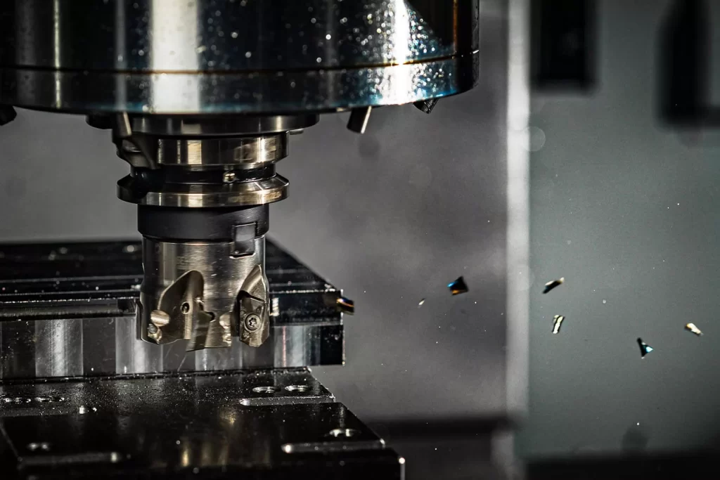
CNC Machining and Turning
- For features of size (Length, width, height, diameter) and location (position, concentricity, symmetry), the tolerance is +/- 0.005” for metals and +/- 0.010” for plastics and composites, in accordance with ISO 2768, unless otherwise specified.
- The as-machined surface finish is 125 Ra or better. Machine tool marks may create a swirl-like pattern on the surface.
- All sharp edges will be broken and deburred by default. Critical edges that must remain sharp should be clearly indicated and specified on the engineering drawing.
- Clear or transparent plastics will exhibit a matte finish or translucent swirl marks on any machined face. Bead blasting will result in a frosted finish on clear plastics.
- Tolerances for foam or similar compressible materials cannot be guaranteed.
- Unless alternative tolerances are agreed upon in your Quote, the general tolerances for orientation and form features are as outlined below. These features include parallelism, perpendicularity, cylindricity, flatness, circularity, and straightness.
CNC Orientation and Form General Tolerance
Table: Parallelism, Perpendicularity, Cylindricity, Circularity, Flatness, and Straightness over Part Length
| Part Length | Orientation and Form Tolerance | Angularity Tolerance |
|---|---|---|
0 to 12″ | +/- 0.005″ | Angularity +/- ½ degree |
12″ to 24″ | +/- 0.010″ | Angularity +/- ½ degree |
24″ – 36″ | +/- 1/64″ (0.016″) | Angularity +/- 1 degree |
36″ – 60″ | +/- 1/32″ (0.031″) | Angularity +/- 1 degree |
Over 60″ | +/- 1/16″ (0.063″) | Angularity +/- 1 degree |
Die Casting
- The typical tolerance for mold machining is +/- 0.010″ during mold fabrication, with an additional +/- 0.001″ per inch accounted for in material shrinkage calculations.
- Requesting tighter as-molded tolerances is possible but may increase tooling costs. Furthermore, achieving many tight tolerances often necessitates manufacturing, sampling, and refining the mold. Xometry will employ a steel-safe milling strategy for critical features.
- Critical features with specified tolerances and surface finishes may require post-machining; such requirements must be specified prior to order during the quotation process. Post-machined features will adhere to Xometry’s CNC manufacturing standards.
- Xometry manufactures die-cast components based on the net-shape (as-cast) model provided by the customer. These models must include appropriate stock allowances for any required post-processing, such as post-machining. Providing both the as-cast 3D model and the final model with accompanying technical drawings is recommended.
- Part-to-part repeatability is typically within +/- 0.004″.
- The as-cast surface finish is typically 64 μin. The standard finish for die-casting is as-cast; a specific Ra value cannot be guaranteed without secondary processing.
- The quoted lead time applies to the first article shipment (T1). The schedule for remaining production is confirmed following first article approval.
- Typical first article shipments consist of five pieces, though quantity may vary based on part size, origin, and material.
- All quotations assume designs incorporate adequate draft, radii, and coring for manufacturability.
- Decisions regarding cores, side actions, and tooling strategy are made by Xometry unless explicitly discussed and agreed upon.
- Gating, ejection, knit lines, and parting line placement are determined at Xometry’s discretion unless explicitly discussed and agreed upon.
- Parting lines on die-cast parts will be visible as a thin seam across the part.
- Cast parts may have one or multiple gate vestiges, which will be trimmed, sheared, or ground off.
- Ejector pin marks will be present on die-cast parts, appearing as small, round flat spots.
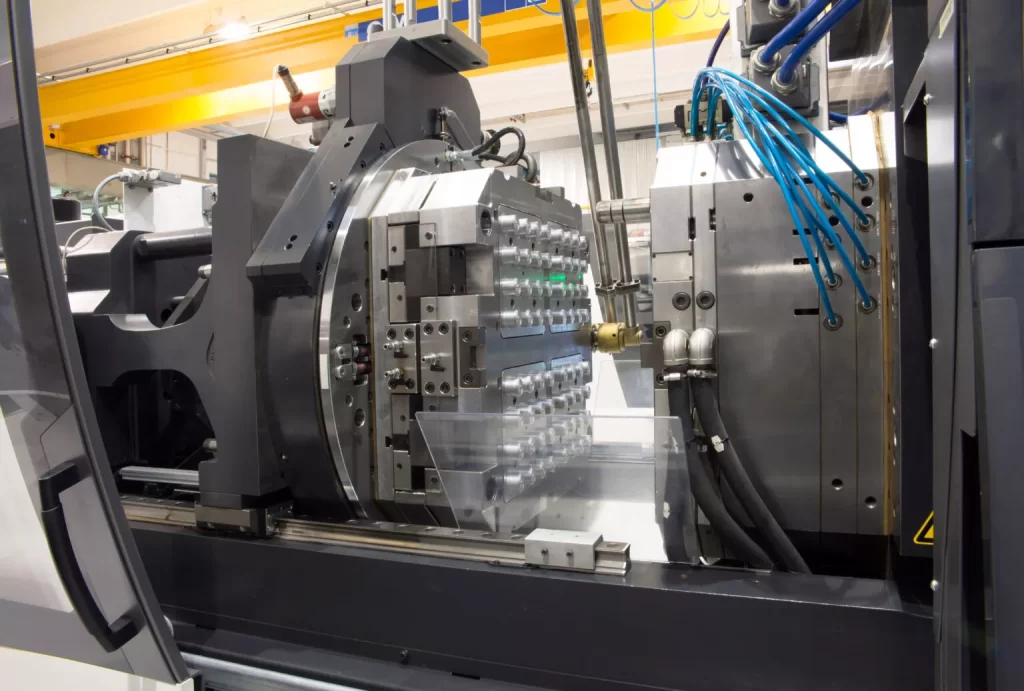
Plastic Injection Molding
- The standard tolerance for mold machining is +/- 0.005″, with an additional +/- 0.002″ per inch accounted for in the material shrinkage calculation.
- Tighter tolerances can be requested, which may increase tooling costs. Additionally, achieving many tight tolerances requires the mold to be manufactured, sampled, and refined. For critical features, Xometry will machine to a steel-safe condition.
- Part-to-part repeatability is typically within +/- 0.004″.
- The stated lead time applies to the first article shipment. The production schedule for the remaining parts is confirmed after the first article is approved.
- Typical first article shipments consist of 10 pieces, though this quantity may vary based on the part’s size, place of origin, and material.
- Xometry cannot guarantee a perfect color match to specific Pantone colors.
- All quotations are provided on the assumption that designs incorporate adequate draft, radii, and coring for manufacturability.
- Decisions regarding cores, side actions, and overall tooling strategy are made by Xometry unless explicitly discussed otherwise.
- The placement of gating and ejection points, as well as knit and parting lines, is determined at Xometry’s discretion unless explicitly discussed and agreed upon.
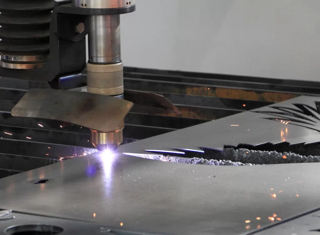
Sheet Cutting Service
- Thickness tolerances are governed by the raw stock material’s own tolerance range and are separate from cutting tolerances.
- Edge-to-edge tolerance on the top face of a plate or sheet is nominally +/- 0.010″. On thicker materials, the bottom face may exhibit a tolerance deviation due to taper inherent in laser or waterjet cutting processes.
- Xometry cannot guarantee flatness callouts for standard sheet-cut materials, except when using ground stock or tooling plate (e.g., MIC6).
- Holes with a diameter of 0.100″ or smaller may be slightly larger on the top face than standard tolerances, due to the cutter piercing the material near the hole’s perimeter.
- A small bump, divot, or different edge condition may be present at the lead-in and lead-out points of a cutting path.
- Pre-finished or textured sheets, such as brushed or polished stock, typically have the cosmetic finish on one side only.
- Protective film may be applied to cut products prior to shipping to prevent damage to cosmetic surfaces.
- The edge condition of sheet-cut materials will exhibit vertical striations rather than a smooth finish. This affects the transparency of edges on clear plastics cut via waterjet.
- Some cut materials may display minor halo discoloration from backsplash (waterjet) or overspray (laser) near the cut edges.
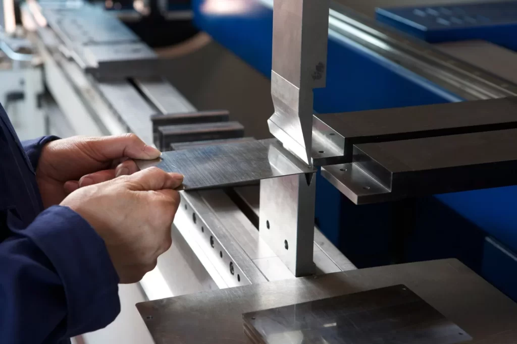
Sheet Metal Fabrication
- Forming and Bending: +/- 0.030″
Bend to Hole or Feature: +/- 0.010″
Linear Dimensions (excluding those relative to bends): +/- 0.010″
Angularity: +/- 2 degrees
Surface Roughness (blank material): Ra 125 μin max
Surface Roughness (TimeSaver): Ra 100 μin max - All sharp edges will be broken and deburred by default. Critical edges that must remain sharp must be clearly noted and specified on the engineering drawing.
- Specific sheet metal designs requiring custom tooling will be flagged for a manual quote. These include hems, curled flanges, rolled sheets, stamped parts, and welded assemblies. If your design incorporates these features, please allow our manual quotation team to review it and provide an accurate cost and lead time.
Sheet Metal Tolerances Reference Table
| Dimension Detail | Tolerance | Image Reference |
|---|---|---|
|
Edge to Edge, Single Surface |
+/- 0.010″ |
A |
|
Edge to Hole, Single Surface |
+/- 0.010″ |
B |
|
Hole to Hole, Single Surface |
+/- 0.010″ |
C |
|
Hole Diameter, Single Surface |
+/- 0.010″ |
D |
|
Bend to Edge / Hole, Single Surface |
+/- 0.010″ |
E |
|
Edge to Feature, Multiple Surface |
+/- 0.030” |
F |
|
Over Formed Part, Multiple Surface |
+/- 0.030” |
G |
|
Bend Angle |
+/- 1 deg |
H |
Metal Stamping
- All quotations are provided under the assumption that designs incorporate sufficient draft, radii, relief cuts, and feature sets to ensure manufacturability with this process.
- Critical-to-function tolerances should be discussed during the quoting phase to guarantee that tooling strategy, inspection gauges (if applicable), and other quality controls are included in the final quote.
- Raw materials like coiled strip are not inherently flat, and this natural variation can be visible on flat stamped or coined components.
- All specified dimensions apply to the inside surfaces of formed features.
- Angular tolerances of +/- 1 degree are typical.
- Stamped parts will be free from splits and other forming defects.
- Features created by punch and die cutting, such as edges, will have straight walls with a small burr on the bottom edge, located approximately one-quarter to one-third down the wall thickness.
- Large burrs and tabs will be removed, but parts are not manually fully deburred before shipment when a standard, as-cut finish is selected.
- Linear dimensions for internal holes will be measured at the shear, or smallest portion of a cut feature.
- Tooling marks are an inherent characteristic of the metal forming process. These marks can be minimized through secondary processing or specific tooling strategies. It is important to identify cosmetic features with Xometry during the quoting or project kick-off phase.
- Material thickness will vary across formed and drawn features.
- Part-to-part repeatability is typically within +/- 0.004″ (with +/- 0.002″ being the usual expectation).
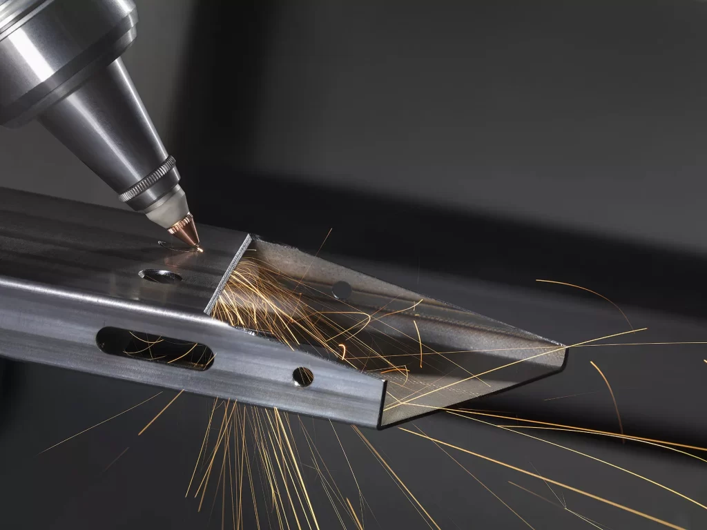
Laser Tube Cutting
- Thickness tolerances depend on the raw stock material’s specifications and are separate from the tolerances achieved during cutting.
- Edge-to-edge tolerance on the outer face of a tube is nominally +/- 0.010″. The inner face on thicker materials may show a tolerance deviation due to the inherent taper from laser cutting.
- Holes with a diameter of 0.100″ or smaller may be slightly larger than standard tolerances due to the piercing action of the cutter near the hole’s edge.
- A small bump or a variation in the edge condition may be present at the start and end points of the cutting path.
- Protective film may be applied to cut products before shipping to protect cosmetic surfaces.
- Large burrs and tabs will be removed, but parts with a standard, as-cut finish are not manually deburred completely prior to shipment.
- Some cut materials may exhibit minor halo discoloration near the cut edges from backsplash or overspray.
Tube Bending
- The manufacturing standards for tube bending are based on draw or mandrel bending techniques. Other methods, such as compression or roll bending, require functional specifications to be mutually agreed upon at the time of order.
- Thickness tolerances are determined by the raw stock material’s specifications and are independent of cutting tolerances. All tolerance measurements assume the stock is in its maximum material condition.
- The overall tolerance for the tube’s outer sheath envelope is typically +/- 0.125″. Tolerances are cumulative across all bent features of the tube.
- Linear dimensions, excluding those relative to bends: +/- 0.010″.
Simple, planar bends: +/- 0.010″.
Multiple, multi-planar bends: +/- 0.030″.
Angularity: +/- 2 degrees.
Tolerance for tube end diameter: +/- 0.020″. - Ovality at a tube bend should not exceed 10% of the averaged measured outer diameter compared to the nominal outer diameter, with 5% to 8% being typical. The formula for ovality is ((Max Ø – Min Ø) ÷ specified Ø) x 100.
- On thicker materials, the inner face may show a tolerance deviation due to the inherent taper from the cutting process.
- Holes with a diameter of 0.100″ or smaller may be slightly larger than standard tolerances due to the cutter’s action near the hole’s perimeter.
- A small bump or a variation in the edge condition may be present at the start and end points of the cutting path.
- Protective film may be applied to cut products before shipping to protect cosmetic surfaces.
- Large burrs and tabs will be removed, but parts with a standard, as-cut finish are not manually deburred completely prior to shipment.
- Some cut materials may exhibit minor halo discoloration near the cut edges from backsplash or overspray.
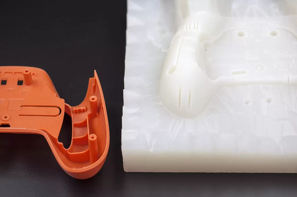
Urethane Casting
- Tolerances are typically +/- 0.010” or +/- 0.003” per inch, whichever value is greater. Irregular shapes or geometries with excessive thickness may lead to dimensional deviations or deflection due to material shrinkage during the process.
- A shrinkage rate of +0.15% can be anticipated, resulting from the thermal expansion of the liquid material and the response of the flexible mold.
- The external surface finish is smoothed to a satin or matte appearance. Grow lines may be visible on internal features or in areas that are difficult to access. Any requirement for polishing or a custom finish must be explicitly defined and mutually agreed upon at the time of order.
- Sharp corners and fine text details may appear slightly rounded.
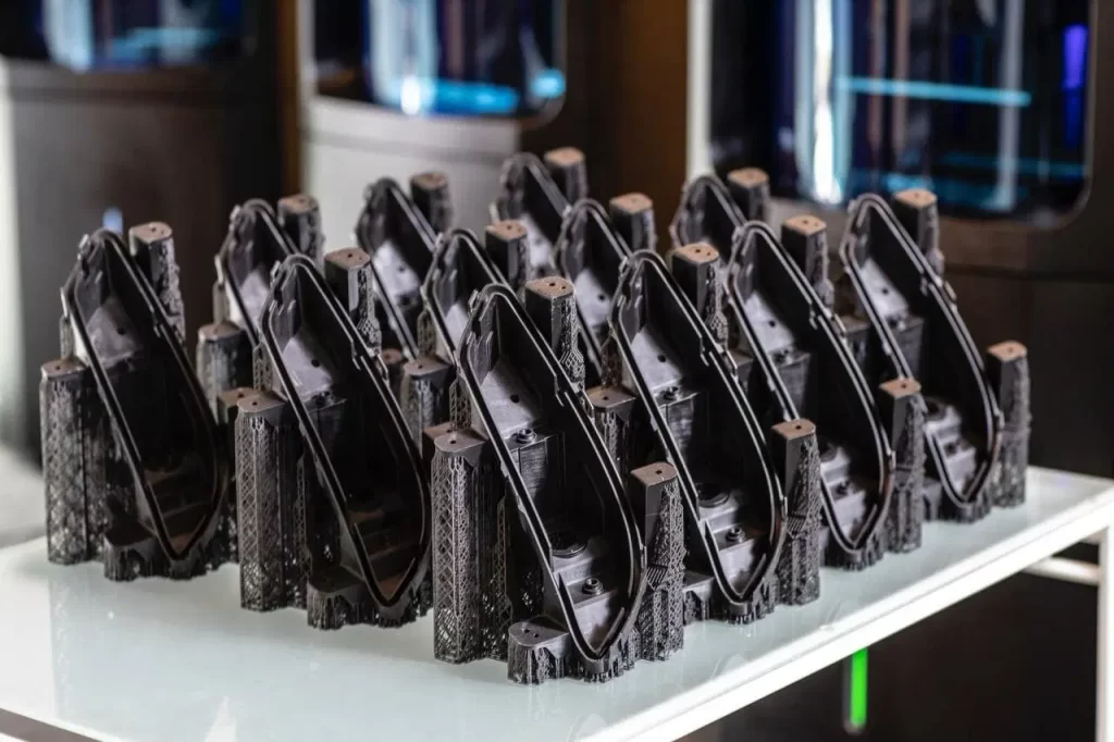
Nexa3D LSPc® 3D Printing
- Tolerances are typically +/- 0.005” in the XY-plane and +/- 0.010” in the Z-plane for the first inch, with an additional +/- 0.002” per inch thereafter. However, Xometry does not guarantee tolerances on the initial production run for a new design.
- Tolerance expectations can differ between materials, such as elastomeric versus rigid types. Tolerances for flexible materials, including xFLEX or xPP405, cannot be guaranteed on their first production run.
- General tolerances apply to parts before any secondary finishing or post-processing, unless otherwise specified. Guaranteed tolerances may be available through a manual quotation review and are approved on a case-by-case basis.
- Upward-facing surfaces may exhibit an additional 0.010-0.020″ of growth due to the support structures required during printing.
- Modeled threads or precision features may have limited functionality as-printed. For optimal performance, tapping or adding threaded inserts is recommended.
- Some materials, like xCE, may become translucent in thin-walled sections. Clear materials, such as xMODEL17, print with a frosted appearance and are generally not suitable for applications requiring optical clarity.
- Certain materials, such as those in the “xFLEX” family, may exhibit off-gassing or have an odor, which can diminish over time.

Polyjet 3D Printing
- A typical tolerance of +/- 0.004″ applies for the first inch, with an additional +/- 0.002″ for each subsequent inch.
- A minimum feature size of 0.050″ can be consistently achieved.
- Rubber-like materials provide an approximation of Shore A hardness values, which may vary depending on the specific geometry.
- Unless otherwise specified, general tolerances apply to parts before any secondary finishing or post-processing steps are performed.
SLA 3D Printing
- The possibility of guaranteed tolerances can be explored through a manual quotation review and requires approval on a case-by-case basis.
- Modeled threads or precision features may exhibit limited functionality in their as-printed state. For optimal performance, tapping or the addition of threaded inserts is recommended.
- The tolerances for Standard and High Resolution options are defined in the table below.
- General tolerances apply to parts prior to any secondary finishing or post-processing, unless otherwise explicitly specified.
Tolerances for SLA, Standard and High Resolution
| Feature | Standard Resolution | High Resolution |
|---|---|---|
|
Tolerance, XY Plane |
+/- 0.005” for the first inch is typical, plus +/- 0.002” for every inch thereafter. |
+/- 0.005” for the first inch is typical, plus +/- 0.002” for every inch thereafter. |
|
Tolerance, Z Plane |
+/- 0.010” for the first inch is typical, plus +/- 0.002” for every inch thereafter. |
+/- 0.010” for the first inch is typical, plus +/- 0.002” for every inch thereafter. |
|
Minimum linear feature size |
Under 0.030” are at risk and under 0.020” will not build. |
Under 0.020” are at risk and under 0.010” will not build. |
|
Minimum radial feature size |
0.035″ |
0.030″ |
|
Layer height |
0.004″ |
0.002″ |
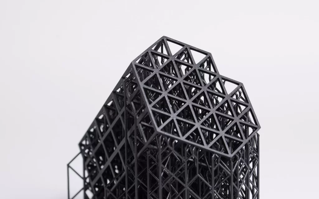
SLS 3D Printing
- For most materials, a typical tolerance is +/- 0.010″ for the first inch, plus +/- 0.002″ for each subsequent inch. For Nylon 12 CF, the typical tolerance is +/- 0.015″ for the first inch, plus +/- 0.002″ per inch thereafter.
- Parts with thick geometries, large flat areas (exceeding 7″), or uneven wall thickness are susceptible to significant deviations or warping due to variable thermal shrinkage and internal stress.
- Modeled threads or precision features may have limited functionality as printed. Tapping or adding threaded inserts is recommended for optimal performance.
- Guaranteed tolerances may be available upon manual quote review and require approval on a case-by-case basis.
- General tolerances apply to parts before any secondary finishing or post-processing, unless otherwise specified.
- Standard-sized holes will be drilled out if accessible. Holes smaller than 0.040″, or those that are irregular or deep, may shrink or close during the sintering process.